STP. Part 1. STP (802.1D-1998)
STP. Part 2. RSTP (802.1w)
STP. Part 3. PVST+
STP. Part 4. MSTP
STP. Part 5. Bridge Assurance
IEEE 802.1s combine the best aspects from both the PVST+ and the 802.1q. The idea is that several VLANs can be mapped to a reduced number of spanning tree instances because most networks do not need more than a few logical topologies.
In other words, MSTP is configurable and more scalable version of PVST+. In MSTP you can define a STP instance for a configurable set of VLANs. By default, there is the Instance 0 (fall back instance) and all VLANs are bound to this instance.
From Cisco.com:
From a technical standpoint, MST is the best solution. From an end-user’s perspective, the main drawbacks associated with a migration to MST are:
– The protocol is more complex than the usual spanning tree and requires additional training of the staff.
– Interaction with legacy bridges can be a challenge.
Protocol Basics
The main enhancement of MSTP is that VLANs can be mapped to a different STP instances. This raises the problem of how to determine that neighboring routers have the same VLAN mappings in order to build a separate tree for these instances.
The IEEE 802.1s committee introduced a concept MST Regions. You can think of a MST Region as the equivalent of BGP/EIGRP Autonomous Systems, which implies common device administration.
For switches to be members of the same Region, the following attributes must match:
– Configuration name
– Configuration revision number
– VLAN-to-instance mapping
The first two attributes are fairly small and they included in MST extension of BPDUs. Last one can be big, so in order to simplify MST Region matching, switch sends hash value of VLAN-to-instance mapping, which is called MST Config Digest. You can verify it using show spanning-tree mst configuration digest command.
There are two types of Instances:
– Internal Spanning Tree (IST) – special STP instance number 0. Exists by default, can not be deleted
– Multiple Spanning Tree Instance (MSTI)
IST
From Cisco.com:
In order to clearly understand the role of the IST instance, remember that MST originates from the IEEE. Therefore, MST must be able to interact with 802.1q-based networks, because 802.1q is another IEEE standard. For 802.1q, a bridged network only implements a single spanning tree (CST). The IST instance is simply an RSTP instance that extends the CST inside the MST region.
Since, by default, all VLANs are mapped to the IST, IST represents IEEE RSTP: all VLANs share single spanning-tree or Common Spanning Tree (CST).
IST (Instance 0) is used to interoperate with RSTP.
MSTIs
The MSTIs are RSTP instances that only exist inside a Region. You can configure Cost and/or Priority values on interface for any MST instance. However, STP timers such as Hello_Time, Forward_Time, Max_Age are configured per Bridge– not per MST instance.
Terminology
IEEE 802.1Q-2003 defines following terms:
– Common Spanning Tree (CST): The single Spanning Tree calculated by STP and RSTP, and by MSTP to connect MST Regions.
– Common and Internal Spanning Tree (CIST): The single Spanning Tree calculated by STP and RSTP together with the logical continuation of that connectivity through MST Bridges and regions, calculated by MSTP to ensure that all LANs in the Bridged Local Area Network are simply and fully connected.
They need to be clarified.
CST is a topology connecting all STP, RSTP Bridges and MST Regions. It is important to emphasize that in CST it is MSTP REGIONS – not MSTP bridges. In CST, MSTP region is treated like a Virtual Bridge. MSTP boundary ports are ports of this Virtual Bridge.
CIST is a single topology connecting all Bridges (STP, RSTP, MSTP) in one active topology. So it is all bridges, literally.
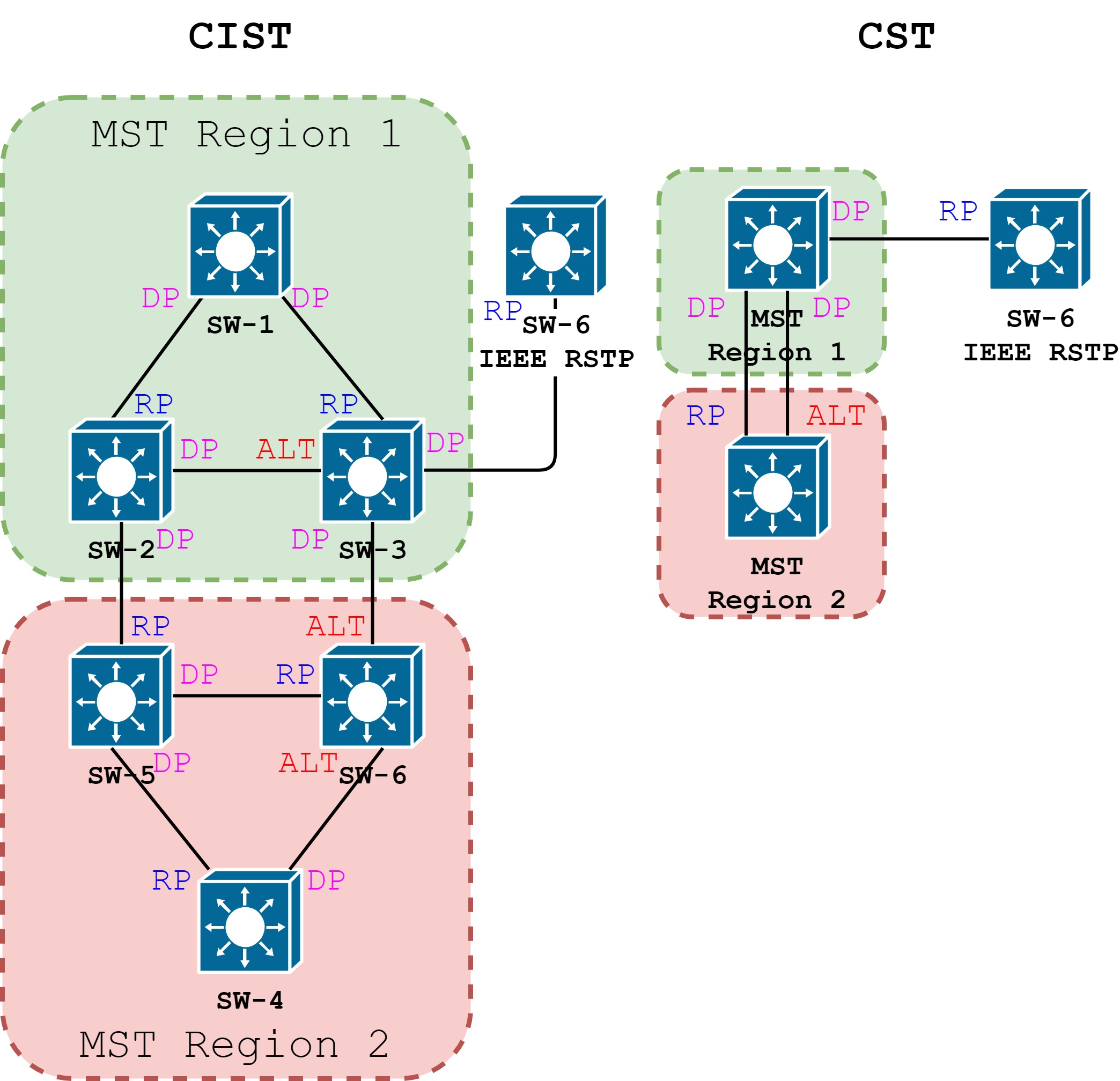
There is an illustration of CST and CIST representation of the same topology in the figure below. For simplicity, Cost of all links is the same and Bridge priority is equal to number of the switch.
Root in MSTP
There are two types of Root Bridges in MSTP:
– CIST Root – one among all MST Regions
– CIST Regional Root – one per MST Region
CIST Root is the Bridge that has the lowest Bridge ID among all regions. If Bridge is the CIST Root it is also the CIST Regional Root.
Every MST Region that does not have CIST Root, elects CIST Regional Root. CIST Regional Root is a Boundary Bridge with shortest external path cost to reach the CIST Root. CIST Regional Root is the root of the IST for the MST Region.
In the example above, the SW-1 is CIST Root and CIST Regional Root in Region 1. SW-5 is CIST Regional Root in Region 2.
MSTP TC
Main advantage of MSTP is TC propagation – any change affecting MSTI in one MST Region will not affect MSTIs in other MST Regions. However, the CIST recalculations affect every MST Region. This is why you may consider not to map all VLANs to CIST.
Main MSTP disadvantage
If you do utilize MSTIs and not map all VLANs to IST, then any changes you make, like add new VLAN to a MSTI, will cause reconvergence of CIST.
MSTP and PVST+
If you have to merge MSTP and (R)PVST+ you need to know that CIST Root must be in MST Region.
Spanning-Tree Dispute Mechanism
RSTP and MST BPDUs include the role and state of the sending port. With this information, switch A can detect that switch B does not react to the superior BPDUs it sends and that switch B is the designated, not root bridge. As a result, switch A blocks (or keeps blocking) its port, thus preventing the bridging loop.
NB
Do not use static VLAN pruning on redundant trunks
MST BPDUs and Interoperability
If this switch receives not an 802.1s (MST) BPDU (a BPDU with the protocol version set to 0 or 2), it sends same BPDUs as BPDU received on this port. Such port is called Boundary Port.
However, the switch does not automatically revert to the MST mode if it no longer receives BPDUs because it cannot detect if switch has been removed from the link.
To restart the protocol migration process (force the renegotiation with neighboring switches), enter the clear spanning-tree detected-protocols command.
MST BPDU
MSTP uses almost same format as RSTP, at least in WireShark it looks the same. However, there is difference purpose of the fields.
Protocol Identifier: Spanning Tree Protocol (0x0000)
Protocol Version Identifier: Multiple Spanning Tree (3)
BPDU Type: Rapid/Multiple Spanning Tree (0x02)
BPDU flags:
Root Identifier:                 CIST ROOT
Root Path Cost:
Bridge Identifier:               CIST REGIONAL ROOT
Port identifier:
Message Age: 0
Max Age: 20
Hello Time: 2
Forward Delay: 15
Version 1 Length: 0
Version 3 Length: 80
MST Extension
    MST Config ID format selector: 0
    MST Config name:
    MST Config revision:
    MST Config digest:
    CIST Internal Root Path Cost:
    CIST Bridge Identifier:       Bridge ID which sent this BPDU
    CIST Remaining hops: 19
    MSTID 2,                      MSTI INFORMATION
        MSTI flags:
        1000 .... = Priority: 0x8
        .... 0000 0000 0010 = MSTID: 2
        Regional Root:
        Internal root path cost:
        Bridge Identifier Priority: 8
        Port identifier priority: 8
        Remaining hops: 19
BTW, if you whant more examples and more detailed explanation, please refer to Pert Lapukhov’s article – Understanding MSTP

Pingback: Blog Summary | cisco networking
Pingback: Multiple Spanning Tree Protocol (802.1s) – MSTP | Networking4all